Microstructure and Porosity Control
Process Control for CGI
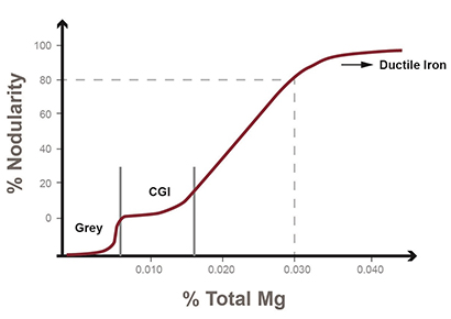
The most important consideration during the production of Compacted Graphite Iron (CGI) is to avoid the formation of flake graphite caused by magnesium fading. During the 10 to 15 minute period from the end of base treatment until the end of pouring, up to 0.003% Mg can be lost due to fading. If the initial starting point of the base treated iron is too close to the abrupt CGI/grey iron transition, the castings produced at the end of the ladle may contain flake graphite. It is not enough to know the solidification behaviour of the iron at the start of casting. The reliable high-volume production of CGI requires a measurement technique that can also determine the graphite shape at the end of casting.
Magnesium Fading
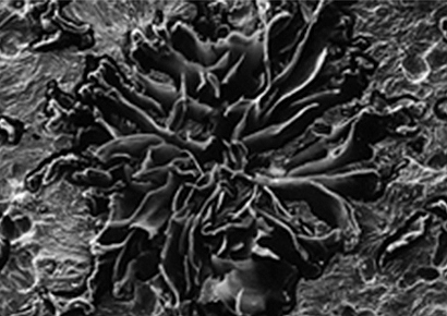
Flake graphite first appears in CGI microstructures as discrete flake patches. In the absence of sufficient magnesium, the graphite begins to grow with a flake morphology. As the solidification front advances radially outward, the active magnesium segregates ahead of the solid/liquid interface. Depending on the initial magnesium content and the solidification rate, the Mg-segregation may result in stable compacted graphite growth around the perimeter of the cell. If the local solidification conditions allow flake patch formation, several such patches will grow and the mechanical properties of the CGI will be reduced by 20~30%.
Nodularity, Flakes and Strength
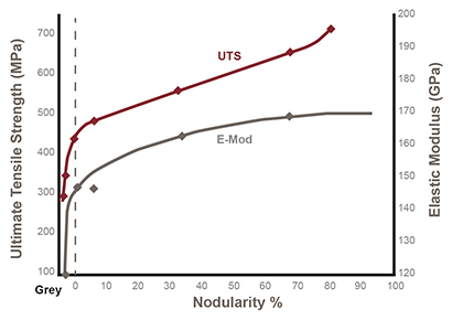
The presence of flake graphite immediately changes the mechanical properties of CGI. The sharp flake edges enable crack initiation while the smooth flake surfaces promote crack propagation by delamination along the flake/metal interface. The presence of even a small amount of flake graphite results in an abrupt 20–30% reduction in tensile strength and elastic modulus. Fatigue strength and impact toughness are also significantly reduced with the onset of flake patch formation. The higher carbon content (3.6–3.8%C) typical of complex CGI castings further reduces the strength in flake containing regions. A fully A-Type flake structure produced with CGI composition would have room-temperature tensile strength of less than 200 MPa.
Microstructure and Porosity Control
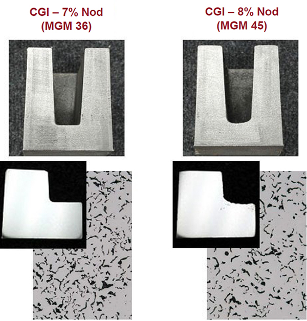
Although most CGI specifications allow 0–20% nodularity, many complex castings such as cylinder blocks and heads incur shrinkage defects before the 20% nodularity limit is reached. As shown in Figure 1, the nodularity within the CGI window can be relatively constant over a range of approximately 0.006% Mg. However, as the Mg-content increases within the range, the onset of shrinkage porosity can begin. This is shown in Figure 4, where two test pieces with similar microstructures have significantly different shrinkage behaviour (flat bottom vs. curved bottom with some internal porosity).
The SinterCast thermal analysis measurement and control process have been specifically developed to control the CGI production at the low-end of the CGI window to provide optimal shrinkage resistance. Although the microstructures in Figure 4 are effectively the same, the SinterCast Modification Index (MGM) values are 36 and 45, providing the resolution needed to measure and prevent porosity defects.
The SinterCast Sampling Cup
The SinterCast thermal analysis measurement is obtained by immersing the patented Sampling Cup into the iron. The immersion sampling ensures that the Sampling Cup and the iron are in thermal equilibrium, preventing any chill-induced solidification and avoiding the oxidation that otherwise occurs when iron samples are poured into thermal analysis vessels. Because the CGI window is so small, it is critical to ensure that all measured differences are due to the solidification behaviour of the iron and not due to variations in the sampling technique. Six separate control checks are performed by the SinterCast software at the start of each analysis to ensure that every sample is obtained consistently.
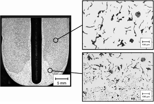
The walls of the SinterCast Sampling Cup are treated with a reactive coating that consumes active magnesium in order to simulate fading. The coating is designed such that the magnesium content in the flow separated region at the bottom of the Sampling Cup will be 0.003% lower than that in the centre of the Sampling Cup. If the initial magnesium content of the iron is too close to the grey iron border, the flow-separated region will solidify as grey iron while the central region solidifies as CGI.
The SinterCast Sampling Cup contains two re-usable thermocouples in a protective steel tube. The first thermocouple is located in the thermal centre of the sample while the second is located at the base of the protective tube, surrounded by the reacted iron. Thus, the centre thermocouple indicates the solidification behaviour at the start of casting while the bottom thermocouple simulates the solidification behaviour at the end of casting.
This patented magnesium-reduction reaction allows foundries to reliably control the CGI production at the low end of the stable CGI window, providing an optimal CGI microstructure and preventing shrinkage defects.
Related Video
Dr Steve Dawson, President & CEO, presents a series of SinterCast Videos to provide overviews of Compacted Graphite Iron, CGI Engine Benefits, the SinterCast technologies for process control and Industry 4.0 traceability, and the overall SinterCast market development.